Use-Case Model
Use-Case Model
Components of Basic Model
There are various components of the basic model:
- Actor
- Use Case
- Associations
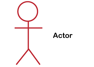
Actor
Use Case
Associations
Advanced Model Components
There are various components of the advanced model:
- Subject
- Use-Case Package
- Generalizations
- Dependencies
Subject
The subject component is used to represent the boundary of the system of interest.
Use-Case Package
We use the model component in order to structure the use case model to make simpler the analysis, planning, navigation, and communication. Suppose there are various actors or use cases. In that case, we can also use use-case packages in order to further structure the use-case model in much the similar way we use directories or folders to organize the information on our hard-disk.
Generalizations
Generalizations mean the association between the actors in order to help re-use of common properties.
Dependencies
In UML, various types of dependencies are defined between use cases.
How to Draw a Use-Case Diagram?
Use-Case
if we want to draw a use case diagram in UML first, we must study the complete system appropriately. We need to find out every function which is offered by the system. When we find out all the system's functionalities then we convert these functionalities into a number of use cases, and we use these use-cases in the use case diagram.
Actor
Associations
Generally, the use-cases diagram is used for:
- Examining the system's requirements.
- Capturing the system's Functionalities.
- We use use-case diagram in order to modeling the general idea behind the system.
- System's Forward and reverse engineering using several test cases.
- Complex visual designing of software.
Basic Use-Case Diagram Symbols and Notations
System
With the help of the rectangle, we can draw the boundaries of the system, which includes use-cases. We need to put the actors outside the system's boundaries.
Use-Case
With the help of the Ovals, we can draw the use-cases. With the verb we have to label the ovals in order to represent the functions of the system.
Actors
Actors mean the system's users. If one system is the actor of the other system, then with the actor stereotype, we have to tag the actor system.
Relationships
With the simple line we can represent relationships between an actor and use cases. For relationships between use-case, we use arrows which are labeled either "extends" or "uses". The "extends" relationship shows the alternative options under the specific use case. The "uses" relationship shows that single use-case is required to accomplish a job.
Use-Case Examples
Use-Case Example-Association Link
Use-Case Example-Include Relationship
Use-Case Example-Extend Relationship
With the help of the extend relationship, we can show the system behavior or optional functionality. We use <<extend>> relationship in order to comprise optional behavior from an extending use-case in an extended use-case. For example, the below diagram of the use-case displays an extend connector and an extension point "Search".
Use-Case Example-Generalization Relationship
Use-Case Diagram-Student Management System
In the above use-case diagram of the student management system, we have two actors and five use-cases. The name of the actors is Student and Teacher. The use-cases represent the definite functionality of the student management system. Every actor interacts with a specific use-case. The student actor is able to check the test marks, time-table and attendance. These are only 3 interactions that can be performed by the student actor; however various use-cases are also remaining in the system.
It is not must that every actor has to interact with each and every use-case, but it can happen.
In the diagram, the name of the second actor is a Teacher. Teacher is an actor that is able to interact with all the system's functionalities. The teacher actor is also able to update the student's marks as well as attendance. Theses interactions of student as well as teacher actors together summarize the whole student management application.


Mga Komento
Mag-post ng isang Komento